¶ PART DESIGN
¶ Introduction
Part design is an app used for creating solid and simple parts by adding and removing material with several tools, such as pads, pockets, holes, threads, and much more. Part Design is one of the most basic ways to create and modify a solid. Thus, the possibilities are reduced to simple models. In this article, some of the more useful tools in Part Design will be explained.
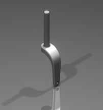

Simple models, like the one on the left, can be done in Part Design. For more complex shapes, such as an aircraft fuselage other apps are used
¶ Create the geometry (Sketching, Pads and Shafts)
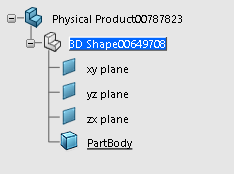
When a part is created, there are some elements of the tree that are given, such as the x, y and z planes, and a PartBody to work on.
To start creating a part it is needed to think of the general shape it has, for example, if it is a pot, it would be good to use a cylinder as a inicial shape, or if it is a phone case, it would be good to start with a thin rectangle.
In order to create the desired 3D solid, first it is needed a 2D drawing. This types of drawings are called sketches, and are the base for every design. Sketches can be as complicated as desired, in the sketching app there are many functions that allow complex shapes, and it will be discussed in a different article. However, it is recommended to keep the sketches as simple as posible, because small changes in geometry done later could cause a mess in the part.
¶ Sketching basics
For most pieces, some basics in the sketching app are enough for the requirements.
- To create a sketch, use the tool positioned sketch, that can be found in the model or the essentials toolbar.
- Select a plane (of the ones given when the piece is created) and CATIA will change automatically to the Sketcher app.
- Create the desired shape selecting the appropiate shape from the Sketch toolbar. Some examples of this shapes are rectangles and circles. Please note that more options are availeable when clicking on the arrow next to a tool.
- If other tool is used, such as lines of profiles, both open or closed sketch can be created. For most shapes is better to keep the skeches closed, however for thin pads if the skechs is open the direction of extrusion can be chosen with the reverse button.
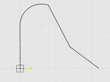
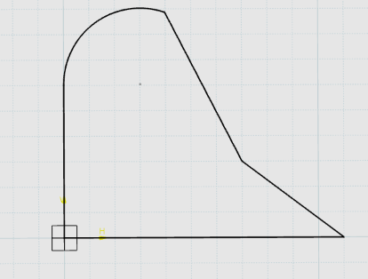
On the left, an example of an opened profile, and the same profile closed on the right image
5. It is good to iso-constrain the sketches, however this will not be explained in this article
6. Once the desired sketch is done, to exit te Sketcher app and go back to the Part Design app click on the Exit App command on the Sketch or Standard toolbar.
¶ Create a solid from a sketch (Pads and Shafts)
There are two main ways to create a solid from a sketch, Pads and Shafts. Both tools are in the essentials or the model toolbar.
¶ Pads
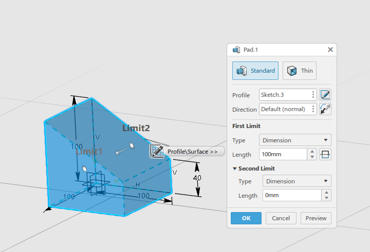
Pads are extrusions of the 2D drawing in one direction. This are the imputs available when creating a pad:
- Profile: Select the sketch that has to be extruded
- Direction: Choose the direction of the extrusion. There are many ways of doing this, such as normal to a selected plane, through a line, of through one of the x, y an z axis. However, the direction selected by default is the one normal to the sketch used.
- First limit: Insert the distance that the sketch has to be extruded in the positive direction (according to the axes). This can be done through parametrization using the right click on the box, and the value can be negative if the extrusion is desired in the opposite direction.
- Second limit: This is the distance in the negative direction. It is setted by default to 0, however it can be modified in the same way as the first limit. Also, if the extrusion is symetrical to both sides of the sketch, the symmetry button, placed next to the length box of the first limit.
Other way of extruding a pad is to make a Thin Pad, this types of extrusion does not completely fill the inside of the geometry. The imputs for this type of extrusion are the same as for the standard one, but the Thin Solid options are added. - Thickness 1: Thickness of the solid that will be created in the inside of the sketch
- Thickness 2: Thickness of the solid that will be created in the outside of the sketch

¶ Shafts
Shafts are rotations of a sketch through an axis. The axis can either be line from the sketch or from other shape. This are the imputs when creating a shaft:
- Profile: Select the sketch that has to be rotated
- Axis : Select the axis (line) it is going to be rotated about
- Angle : Select the degrees (or other unit) that the sketch is rotated. It is setted by default to 360 deg (a full rotation). This number can be also set as a parameter. There are other options for types of angles, however, the angle one is the most used

Similarly to the pad, the shaft also has a thin option, with the same options as the standard and the same definitions for thickness 1 and thickness 2.
¶ Add features to the part
¶ Pockets and holes
Pockets and holes remove material from an existing part, the main diference is that holes are round, and you will need a point and a radius, while pockets are done with a sketch and can have different shapes. They can both be found on the essentials or the model toolbar.
¶ Pockets
The elements required for creating a pocket are a solid body and a profile, even though there are more options available. The input for creating a pocket are:
- Profile: Select the profile that is going to cut the body. The button on the very right of this box allows to create the pocket to the outside part of the profile
- Direction: Select the direction that the cut is going to be done. This is not mandatory, if no direction is introduced it will be perpendicular to the sketch
- First and second limit: These options work the same way as in the pads, select the distance that is cut in each direction.

Simillarly to pads, it exist a option to create a Thin pocket, which doesn't remove all the material from the inside or the outside of the profile. Simillarly to the pads, there are two more options for thickness in both drirecions.
In addition there are two more options. Neutral fiber indicates that material is deleted equally to both sides of the profile, so if the selected thickness is 10mm, then a thickness of 5mm is deleted to both sides. Merge ends merges uneven ends of the profile with the surrounding material.

¶ Holes
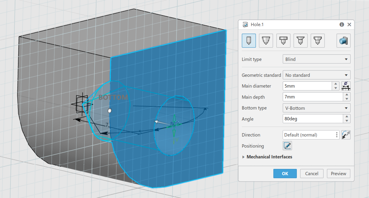
Holes also remove material from an existing body, however the shape removed is always a circle or sililar. To locate a hole click an existing surface. If the surface is even the hole will be created on the clicked point. if its not, a tangent plane to the surface will be crated on the surface and it will be used as a support to create the hole. To increase the precission its recommended to position a point in the desired location and select it when creating the hole. The positioning of the hole can be also changed selection the sketh button at the bottom
It emulates real holes made by a drill, so several types of holes are given as an option. Some of the options are geometric standard for drilling holes for predefined bolts, defining the bottom shape and angle, changing the diameter, depth and direction of the drilling. Optionally you can add a thread on the drilled hole by clicking the thread button on the top right corner.
¶ Corner reliefs (Edge fillets, chamfers and drafts)
Corner reliefs are used to avoid sharps edges that might be a problem during manufacturing, or for other reason like asthetics. All corner relief options can be found in the refine toolbar.
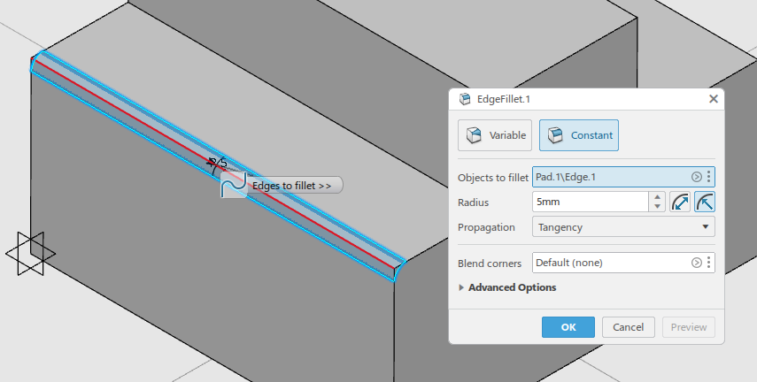
Edge fillets
The edge fillet is a round cut of a corner. This can be applied to any angle of a corner. The main elements required for a fillet are:
- Objects to fillet: Select the edges that you want to fillet. It can be selected as many edges as desired.
- Radius: The radius of the fillet
There are other advanced options and a variable type of fillet, but this will not be discussed on this article.
With this basic tools some interesting shapes can be crated, and is usually enough for very simple projects. More detalied information about Part Design app can be found in CATIA official documentation